4 - Getting Started EVIC
- TechOps-JV (Unlicensed)
- AI-JEDI
Principle of Operation
Functional Description
EVIC decodes CAN bus data into human-readable form and displays it onto the HMI screen. EVIC is a standalone display device and is configurable with our Studio Interface Kit.
Wiring
EVIC uses the following 3 Molex connectors and crimp terminals:
| Connector | Manufacturer | Pins | Connector Part Number | Terminal Part Number |
|---|---|---|---|---|
Power / CAN / Digital Input | Molex / Tyco | 20 | 31408-1200 | 1393366-1 |
| Analog Input | Molex / Tyco | 12 | 31408-1120 | 1393367-1 |
| Digital Output | Molex / Tyco | 12 | 31408-1120 | 1393367-1 |
You can purchase these separately through Digi-key or Mouser, or request for them when you place your order.
This universal crimper tool can be used for the terminals.
General Set-up
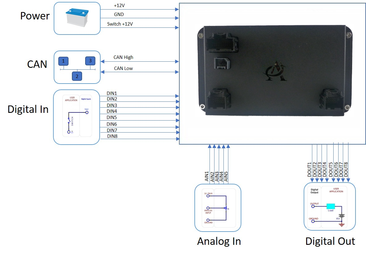
To get started, wire Pins 1 and 3 (VBAT) to +12V or +24V and Pin 2 (GND) to Ground. Once power is applied, the default splash screen will be displayed and will transition to the Graphical User Interface (GUI) application.
Default Splash

The default splash screen is configurable. To replace the default splash screen image, Andromeda's Flasher Tool is available to make this change.
Graphical User Interfaces
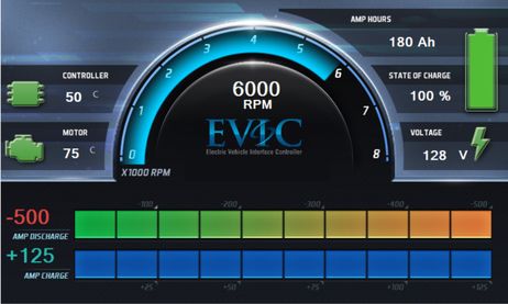
The start-up GUIs will appear as shown below. These GUIs are configurable through our Studio Interface Kit (SIK).
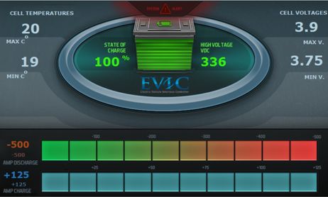
EVIC.Combo
EVIC.BMS