IO Mapping
Introduction
There are multiple input and output (IO) interfaces available on EVIC. The Studio Interface Kit allows you to assign them to labels and picture boxes.
Assigning Digital Inputs
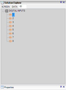
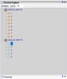
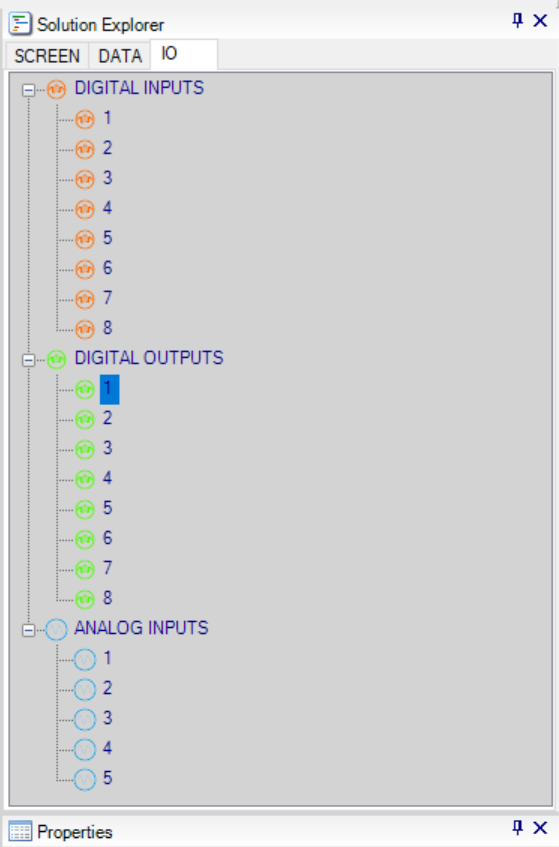
1. Digital inputs are viewable in the Solution Explorer tab labeled "IO". The number of digital inputs available on EVIC is 8. You can view EVIC's interfaces to see what is available.
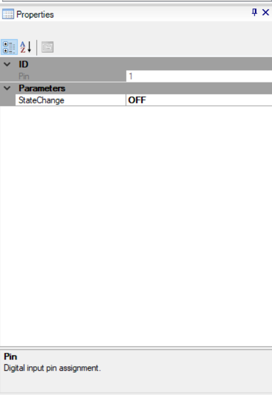
2. There is a configurable property available for each digital input.
- The "StateChange" property determines the behavior of the digital input. The property can be set either to ON or OFF to determine when to read the digital input and to take action.
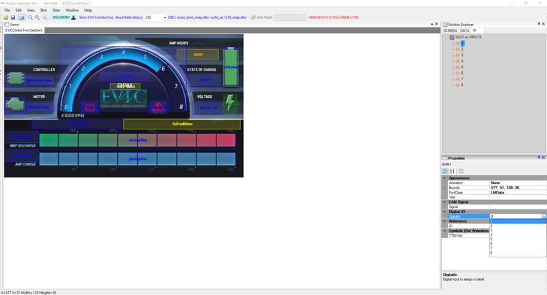
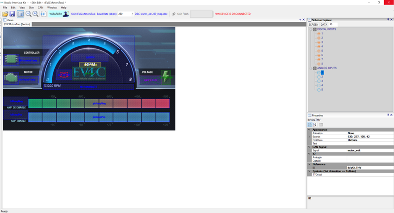
3. You can drag and drop a digital input over to the skin's graphical canvas and assign it to a specific control label or picture box. This can be easily achieved by clicking on the digital input and dragging it over. There is also an option to select each digital input from the "DigitalIn" drop-down menu within the "Properties" window.
Once a digital input has been assigned to a label or picture box, a orange mesh will highlight the control.
4. To enable a digital input, you need to set the property "Animation" to anything other than "None" to have a label or picture respond to its switching states. For example, if you want to have text appear on a label, assign a digital input to a label and set its"Animation" property to "TellTale". The label's text will appear or disappear when the digital input turns ON or OFF.
Note: You can assign each digital input to multiple picture boxes and labels.
Assigning Analog Inputs
1. Analog inputs are viewable in the Solution Explorer tab labeled "IO". The number of analog inputs available on EVIC is 5. You can view EVIC's interfaces to see what is available.
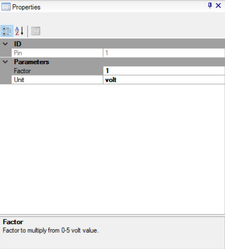
2. There are configurable properties for each analog input.
- The "Factor" property allows you to multiply a value from the voltage signal received from the analog input. For example, there is a default value of "1", so the raw voltage from the analog-digital-converter (ADC) will be displayed within a range of 0-5V.
- The "Unit" property allows you to set the text you want to be displayed with the value.
3. You can drag and drop an analog input over to the skin's graphical canvas and assign it to a specific control. This can be easily achieved by clicking on the analog input and dragging it over. There is also an option to select each analog input from the "AnalogIn" drop-down menu within the "Properties" window.
Once an analog input has been assigned to a label or picture box, a violet mesh will highlight the control.
Note: You can assign each analog input to multiple picture boxes and labels.
Assigning Digital Outputs
1. Digital outputs are viewable in the Solution Explorer tab labeled "IO". The number of digital outputs available on EVIC is 8. You can view EVIC's interfaces to see what is available.
2. There are configurable properties for each digital output.
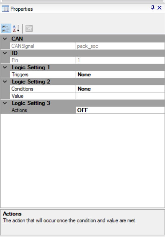
- The "CANSignal" property assigns any of the CAN signals available in your skin project to use in the Logic Setting categories 1, 2 and 3.
- The "Triggers" property assigns any of the available analog inputs, digital inputs, or CAN signals in your skin project to determine what method to use prior to triggering the digital output.
- The "Conditions" property assigns different logic statements (e.g., >=, <=, >, <) to compare the user-defined Value property with the actual analog or digital input's data or CAN signal data that is assigned in the Triggers.
- The "Value" property is a user-defined value to use in conjunction with the Conditions and Triggers property.
- The "Actions" property will determine the behavior of the digital output to either turn it ON or OFF once the user-defined Conditions property is met.