Connectors
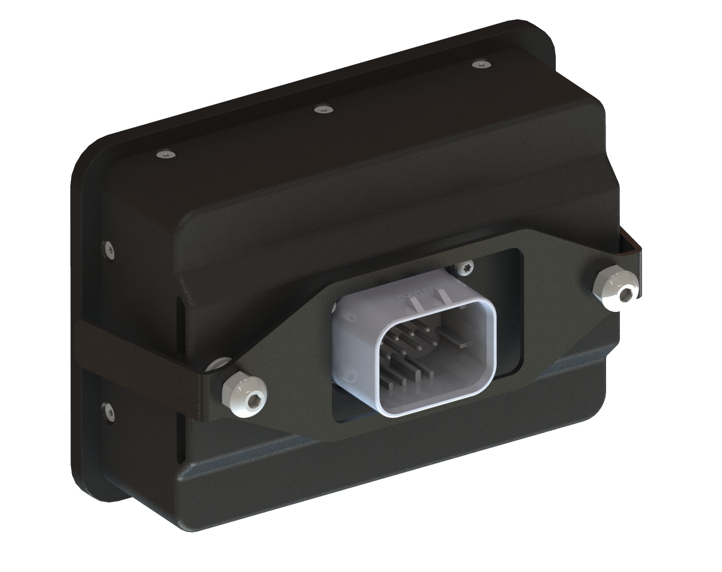
IG is equipped with a rugged sealed connector. On the back of the device, there is a 14-pin AMP SEAL female connector.
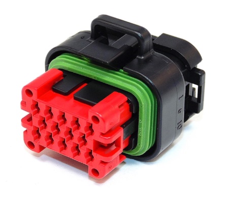
The mating connector is shown below. TE Connectivity part number 776273-1. The terminal's part number is 770520-1.
This universal crimper tool can be used for the terminals.
Harness Connections
PIN | Name | Type | What to Connect | Maximum Rating |
1 | +12V POWER | Power | Constant power source | +36V |
2 | +12V SWITCH | Power | Power switch source | +36V |
3 | GND | Power | Power source return | |
4 | ||||
5 | RXD_EXT | Comm | RS232 | - |
6 | TXD_EXT | Comm | RS232 | - |
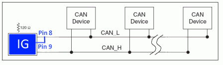
7 | CAN1_H | Comm | CAN High | - |
8 | CAN1_L | Comm | CAN Low | - |
9 | CAN_TERM | - | Wire to Pin 8 to terminate CAN lines to 120-ohm resistor | - |
10 | V5P0_USB | Programming | USB Type-A | - |
| 11 | USBPHY1_N | Programming | USB Type-A | |
| 12 | USBPHY1_P | Programming | USB Type-A | |
| 13 | BOOT1 | Short Pins 13 and 14 to place IG into boot mode | ||
| 14 | BOOT0 | Short Pins 13 and 14 to place IG into boot mode |
Table 1: Connector pinout and wiring information |
Interfaces
CAN Channel
IG can operate as a single node or be included in a multi-node CAN bus network. IG can be configured as either terminated or non-terminated on the network. In order to terminate IG, you must short pins 9 and 8 on the main connector.
Baud Rate
IG is configured by default at 250 kbps baud rate. IG's configurable baud rates are 125, 250, 500 or 1000 kbps.
Note: If data does not appear or is displayed intermittently, please verify CAN baud rates are set correctly for all components on the network.