...
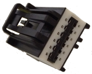
Terminals: Molex part number 1393367-1
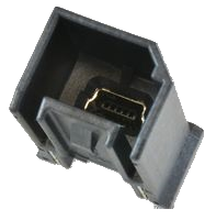
J4 - Mini-B USB Connector - Programming cable used for SIK
The cable is provided with the purchase of EVIC.
Harness Connections
| J1 - MAIN CONNECTOR PINOUT | ||||
PIN | Name | Type | What to Connect | Maximum Rating |
1 | +12V POWER | Power | Constant power source | + |
24V | ||||
2 | GND | Power | Power source return | - |
3 | IGN | Power | Switch |
power → Turns the brightness of the screen to OFF | + |
24V | ||||
4 | CAN_HIGH | Comm | CAN High | - |
5 | CAN_LOW | Comm | CAN Low | - |
6 | DIN 7 | Digital Input | Switches, buttons | +18V |
7 | DIN 6 | Digital Input | Switches, buttons | +18V |
8 | DIN 1 | Digital Input |
| Backlight control → Turns the brightness of the screen to HALF | +18V | |||
9 | DIN 2 | Digital Input | Switches, buttons | +18V |
10 | DIN 3 | Digital Input | Switches, buttons | +18V |
11 | DIN 4 | Digital Input | Switches, buttons | +18V |
12 | DIN 5 | Digital Input | Switches, buttons | +18V |
13 | RXD_EXT | Comm | RS-232 (diag only) | |
14 | TXD_EXT | Comm | RS-232 (diag only) | |
15 | RTS_EXT | Comm | RS-232 (diag only) | - |
16 | CTS_EXT | Comm | RS-232 (diag only) | |
17 | DIN 8 | Digital Input | Switches, buttons | +18V |
18 | AIN_5_Signal | Analog Input | Sensor signal | +5V |
19 | BOOT 1 | Boot Mode | Short Pins 19 and 20 to place EVIC into boot mode | |
20 | BOOT 2 | Boot Mode | Short Pins 19 and 20 to place EVIC into boot mode |
| J2 - ANALOG INPUT CONNECTOR PINOUT | ||||
| Pin | Name | Type | What to Connect | Rating |
|---|---|---|---|---|
1 | AIN_1_Signal | Analog Input | Sensor signal | +5V |
| 2 | AIN_1_Reference | Power | 5V power output | - |
| 3 | AIN_1_Ground | Power | 5V reference ground | - |
| 4 | AIN_2_Signal | Analog Input | Sensor signal | +5V |
| 5 | AIN_2_Reference | Power | 5V power output | - |
| 6 | AIN_2_Reference | Power | 5V reference ground | - |
| 7 | AIN_3_Signal | Analog Input | Sensor signal | +5V |
| 8 | AIN_3_Reference | Power | 5V power output | - |
| 9 | AIN_3_Reference | Power | 5V reference ground | - |
| 10 | AIN_4_Signal | Analog Input | Sensor signal | +5V |
| 11 | AIN_4_Reference | Power | 5V power output | - |
| 12 | AIN_4_Reference | Power | 5V reference ground | - |
| J3 - DIGITAL OUTPUT CONNECTOR PINOUT | ||||
| Pin | Name | Type | What to Connect | Rating |
|---|---|---|---|---|
| 1 | DOUT_1 | Digital Output | LED's, Relays, Buzzers | 2A |
| 2 | DOUT_2 | Digital Output | LED's, Relays, Buzzers | 2A |
| 3 | DOUT_3 | Digital Output | LED's, Relays, Buzzers | 2A |
| 4 | DOUT_4 | Digital Output | LED's, Relays, Buzzers | 2A |
| 5 | DOUT_5 | Digital Output | LED's, Relays, Buzzers | 2A |
| 6 | DOUT_6 | Digital Output | LED's, Relays, Buzzers | 2A |
| 7 | DOUT_7 | Digital Output | LED's, Relays, Buzzers | 2A |
| 8 | DOUT_8 | Digital Output | LED's, Relays, Buzzers | 2A |
| 9 | GND | Power | Power source return | - |
| 10 | GND | Power | Power source return | - |
| 11 | GND | Power | Power source return | - |
| 12 | GND | Power | Power source return | - |
Interfaces
Digital Inputs
EVIC is equipped with 8 digital inputs that can determine input states from switches or buttons. Digital inputs 1 through 7 are triggered by sourcing +12V. Digital input 8 is triggered by sinking to GND.
...
 If you have not correctly mapped the digital inputs to skin graphics graphic labels or images, then nothing will occur when switching these pins.
...
EVIC is equipped with 8 digital outputs that are low-side switches. They are designed for a variety of applications including LEDs, external relays or buzzers.
...
EVIC is equipped with 5 analog inputs (1 on the main connector, 4 on the analog input connector) at 12-bit resolution. They can be used to read measurements from many sensors such as temperature, potentiometer or brake transducers. There are reference 5V and ground outputs provided on the analog input connector to supply power to sensors if necessary.
...