3 - Interfaces ATDM
Sections in this page:
Overview
The tables below highlight the various interfaces on ATDM.
Main Connector
The main connections used on ATDM are automotive grade style from Ampseal Connectors.
The following pin designations are described in the table below:
| 35-PIN | |
| Pin | Description |
|---|---|
| 1 | Digital Input 1 |
| 2 | Digital Input 2 |
| 3 | Digital Output 1 |
| 4 | Digital Output 2 |
| 5 | Digital Input 3 |
| 6 | Digital Output 3 |
| 7 | Digital Output 4 |
| 8 | Digital Input 4 |
| 9 | Analog Input 1 |
| 10 | Analog Input 2 |
| 11 | Digital Input 5 |
| 12 | Digital Input 6 |
| 13 | RS485_H |
| 14 | RS485_L |
| 15 | GND |
| 16 | Supply Voltage |
| 17 | Analog Input 3 |
| 18 | GND |
| 19 | Analog Input 4 |
| 20 | Analog Input 5 |
| 21 | GND |
| 22 | Analog Input 6 |
| 23 | Supply Voltage |
| 24 | GND |
| 25 | Digital Input 8 |
| 26 | CAN1-L |
| 27 | CAN1-H |
| 28 | Digital Input 9 |
| 29 | Digital Input 7 |
| 30 | Ignition |
31 | Digital Input 10 |
| 32 | CAN2-L |
| 33 | CAN2-H |
| 34 | Digital Input 11 |
| 35 | Digital Input 12 |
Breakout Connector
The breakout connections used on ATDM are automotive-grade style from Ampseal Connectors.
The following pin designations are described in the table below:
| 14-PIN | |
|---|---|
| Pin | Description |
| 1 | Digital Output 5 |
| 2 | Digital Output 6 |
| 3 | Digital Output 7 |
| 4 | Digital Output 8 |
| 5 | Supply |
| 6 | GND |
| 7 | GND |
| 8 | Audio Out (Line) L |
| 9 | Audio Out (Line) R |
| 10 | Audio Mic In |
| 11 | Video 1 |
| 12 | Video 2 |
| 13 | Video 3 |
| 14 | Video 4 |
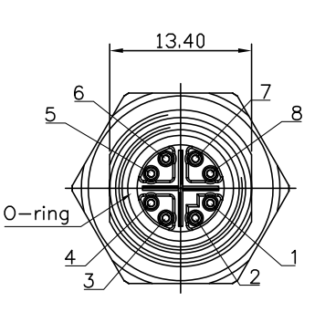
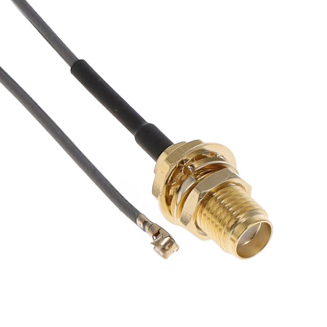
Antenna and Ethernet Connectors
The antenna connection is IPEX MHF1 to SMA female. The ethernet is rugged and made to be dust and waterproof tight. The following designations are described in the image below:
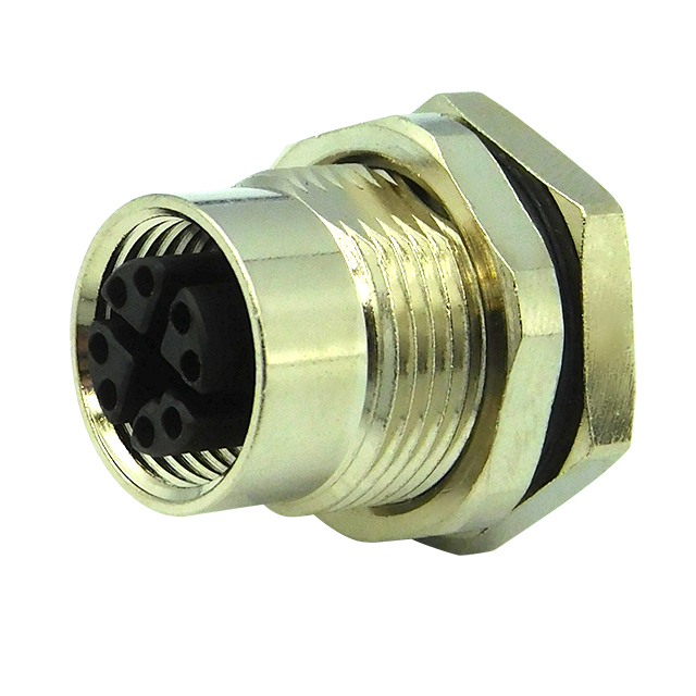
Antenna 3x Ethernet 2x